Post Stastics
- This post has 953 words.
- Estimated read time is 4.54 minute(s).
The “Negative Load” Problem
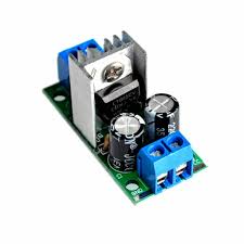
Standard linear regulators, like the ubiquitous LM7805, are designed to be “sinks” of power. They take a higher voltage and drop it down, pushing current out of their output pin to power your circuit. However, they are effectively “one-way valves.”
In a modern project—especially one involving motors, large inductors, or external pull-up resistors—your circuit can suddenly become a source rather than a load. When a motor brakes or an inductive solenoid fires, it can kick current back into the 5V rail. Because a standard regulator cannot “pull” that voltage back down, the rail voltage climbs. This overvoltage can reset microcontrollers, garble data, or even fry sensitive logic ICs while the regulator sits helpless.
Why Stick with Linear Regulators?
In an era of high-efficiency switching regulators, you might wonder why we still use the LM7805. Linear regulators and LDOs hold several massive advantages:
- Low Noise & EMI: Switching regulators chop current at high frequencies, creating electromagnetic interference. For sensitive analog circuits or precision ADCs, the electrical “silence” of a linear regulator is unmatched.
- Simplicity: No complex inductor selection or high-frequency layout headaches.
- Fast Load Regulation: Linear regulators often respond to sudden load changes faster than budget switching controllers.
Expanding into the Two-Quadrant Domain
To fix the “one-way” shortcoming, we move toward a Two-Quadrant Power Supply. In power electronics, a “Quadrant” refers to the relationship between Voltage (V) and Current (I).
- Quadrant I (Sourcing): Positive Voltage, Positive Current. The regulator gives power.
- Quadrant IV (Sinking): Positive Voltage, Negative Current. The regulator absorbs power.
By adding a “Current Dump” circuit to a standard linear regulator, we create a hybrid system. It provides the ultra-low noise of a linear supply for normal operation but acts as a high-speed electronic sink the moment the rail tries to spike.
The Solution: A 5V Rail Current Dump
This circuit acts as a precision “Safety Net.” It sits in a high-impedance state (invisible) until the rail hits a specific threshold, then snaps into action to dump the excess energy to ground.
How it Works
- Sensing: A voltage divider (R25, TRIM_1, R40) scales the 5V rail. When the wiper reaches exactly 2.5V, the TL431 precision reference (U6) begins to conduct.
- Switching: The TL431 pulls the base of Q16 (BC557) low, turning it on. This provides gate voltage to Q17 (AO3400A), a high-speed N-Channel MOSFET.
- Dumping: Q17 connects a bank of four 56 ohm resistors (R27 – R30) in parallel to ground. This 14 ohm load “dumps” the excess current.
- Feedback: As current flows through the dump resistors, the voltage drop across R42 triggers Q18, lighting an LED. This isn’t just a power light; it’s a diagnostic tool that confirms the circuit is actively absorbing energy.
Technical Specifications
- Trip Point: Adjusted via TRIM_1 to 5.05V.
- Max Sink Current: I = 5.05V/14 ohms ~360mA.
- Response Time: Built to react in under 2ms to protect fast digital logic.
Engineering for the Real World: The “Tug-of-War”
There is a hidden danger in this design: Component Tolerance. A standard LM7805M datasheet specifies a regulation range between 4.8V and 5.2V.
If your specific regulator naturally sits at 5.15V but you’ve set your current dump to trigger at 5.05V, the two circuits will enter a destructive “tug-of-war.” The regulator will try to push the voltage up, and the dump will try to pull it down. This results in a massive 360mA current sink being wasted as pure heat on the regulator output!
Calculating the “Safe Zone”
In our specific build, we used a linear regulator confirmed through testing to regulate at a very precise 5.015V, allowing us to set a tight 5.05V clamp. Our circuit was a one-off. However, for a production-ready design, you must perform the following:
- Read the Datasheet: Note the “Worst Case” output voltage for your regulator.
- Physical Testing: Measure output under light, nominal, and heavy loads across a sampling of devices. Some regulators “creep” upward when they get hot or under light loads.
- Calculate the Margin: Ensure your TRIM1 range covers at least 5% above and below your regulator’s highest and lowest measured outputs. Its helpful to ensure your nominal trip point is ~center of your trim.
The Formula
To find your Trip Voltage (Vtrip), use:
Vtrip = 2.5V * (1 + (Rtop /Rbottom_total)
Where Rbottom_total is the sum of your fixed bottom resistor (R40) and the resistance of the potentiometer (TRIM1).
| Target Rail | Typical Reg. Max | Recommended Trip | Rtop (Fixed) | TRIM1 (Pot) | Rbottom (Fixed) |
| 3.3V | 3.43V | 3.50V | 2.2k | 1k | 4.7k |
| 5.0V | 5.20V | 5.30V | 7.5k | 2k | 5.6k |
| 12.0V | 12.5V | 12.7V | 39k | 10k | 8.2k |
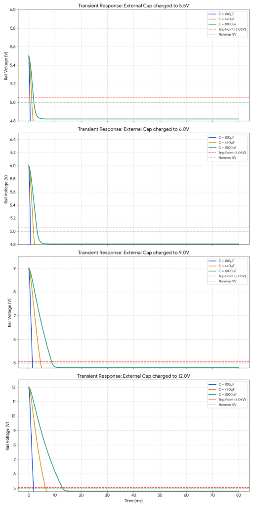
Performance & Stress Testing
To see how this handles real-world “energy injections,” we simulated connecting capacitors charged to 5.5V, 6V, 9V and even 12V to the 5V rail.
As the graphs show, the circuit successfully “catches” the rail every time. For a 12V spike, the instantaneous power hits 10.3W. While these are 1W resistors, their thermal mass allows them to handle these millisecond bursts easily.
Safety & Thermal Management
Because this circuit converts excess electrical energy into heat, thermal management is key:
- Transient vs. Continuous: If you expect the “dump” to last more than a second, use a TO-220 MOSFET with a heatsink.
- PCB Layout: Use wide copper traces for the dump resistors to allow the board itself to act as a heatsink.
Bill of Materials (BOM)
| Reference | Part | Description |
| U6 | TL431DBZ | Precision Reference (2.5V) |
| Q17 | AO3400A | N-Channel MOSFET (5.8A) |
| Q16 | BC557 | PNP Transistor |
| R27-30 | 56 Ohms | 1W Power Resistors |
| TRIM1 | 2k Ohms | Trimmer Potentiometer |
Conclusion
For less than $2.00 in parts, this hybrid approach gives you the best of both worlds: the ultra-low noise of a linear regulator and the ruggedness of a two-quadrant supply. By testing your specific regulator and calculating your divider range appropriately, you can build a power rail that is truly bulletproof.