- Building Machines In Code
- Building Machines in Code – Part 2
- Building Machines In Code – Part 3
- Building Machines In Code – Part 4
- Building Machines In Code – Part 5
- Building Machines In Code – Part 6
- Building Machines In Code – Part 7
- Building Machines In Code – Part 8
- Building Machines In Code – Part 9
Post Stastics
- This post has 4016 words.
- Estimated read time is 19.12 minute(s).

Today’s Project
NOTICE: Today’s Code will only work under Python 3.10 and later.
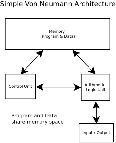
In this episode, we will build a new system using a processor with Von Neumann Architecture. We will also be splitting our system into various files and classes to organize our system better. The Memory will no longer be part of the CPU. Also, this time our system will provide a console for I/O.
The project today is a step up from modeling a processor to modeling a small system. In later projects, we will leverage the knowledge gained here to build more complex systems. The project we will approach today is building a small computer system complete with a crude I/O sub-system. This system is called the Tiny-T. (In case you didn’t get the reference, our first processor was the Tiny-P and was a Havard Architecture – An architecture where program and data are segregated. The Pilgram John Havard is Harvard’s mascot. The processor used in today’s project is the Tiny-T. John Von Neumann spent much of his professional life teaching at Princeton and Princeton’s mascot is the Tiger.)
This processor will have much in common with our previous offering. However, its program and data memory will be consolidated into a single memory. Programs are just specialized data. The program isn’t what is special. It is the way we interpret the data that makes it special. For example, a photo is just one’s, and zeroes that represent an image. But that same data could be interpreted as music. You can find services to do this interpretation for you on the internet. In the same way, our programs are just one’s and zeros that are interpreted as CPU commands.
Advantages & Disadvantages of Von Neumann Architecture
One advantage of the Von Neumann Architecture is that our programs can be modified at run time. A smart programmer can program code that changes itself over the life of the program. This can lead to some very powerful effects. The downside to the Von Neumann Architecture is that the code can be modified at runtime. Yes, I just claimed this is a strength and a weakness. Because this leaves the program susceptible to malicious programs that can modify our program and steal its data and code. Computer systems today are still dealing with this issue because of their architectural choices.
The Tiny-T Processor
Today, our task will be to develop our Tiny-T processor. The instructions supported by the Tiny-T will look very familiar to you as they are nearly identical to the TIny-P. However, where our Tiny-P used decimal encoding of the opcode and operands, the Tiny-T will use a hexadecimal encoding. The instructions will also be 16-bits. With the upper 12-bits containing the opcode, and the lower 12-bits containing the operand or zero if no operand is needed.
Memory
As you might expect, using 12-bits for the operand allows the processor to directly address up to 4096 memory locations. This means we can write far larger programs for the Tiny-T than we could for the Tiny-P with its 100 memory cells.
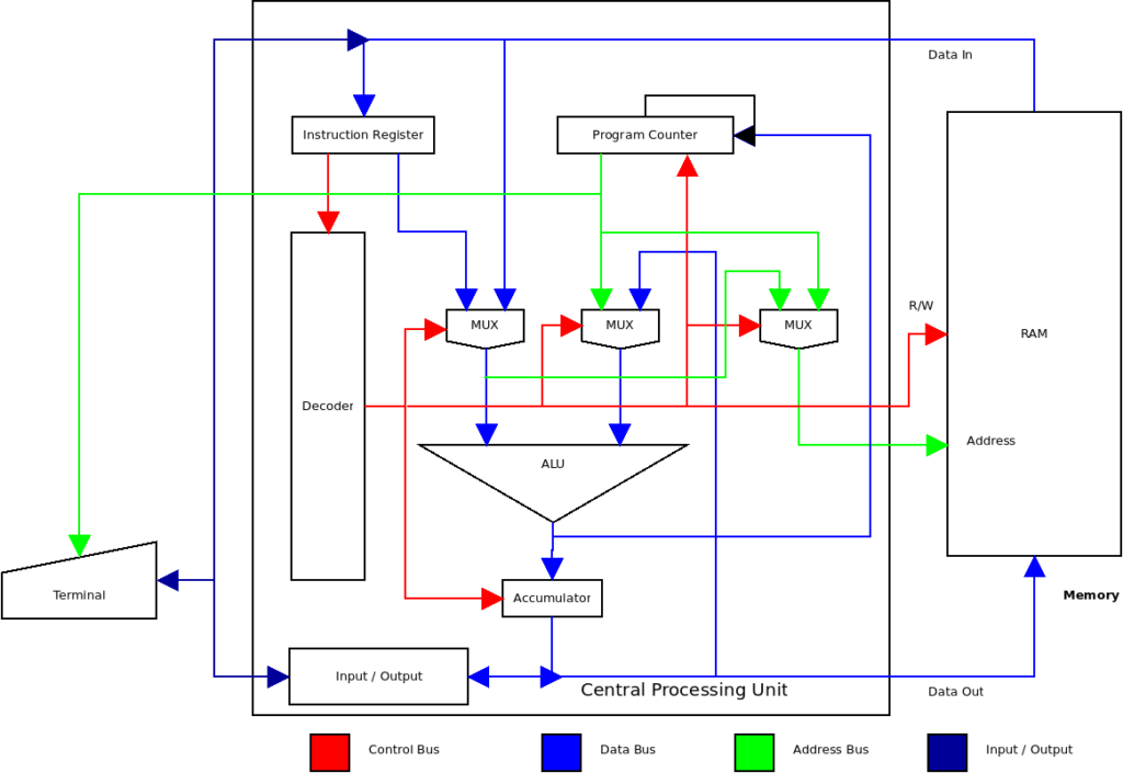
The block diagram above shows the Tiny-T system. As you can see there is no Read Only Memory for program storage. Programs will be stored in RAM. Also, note that we have an I/O terminal. This will be a very crude console but can be upgraded later.
Tiny-T ISA
Let’s get started with the CPU. Our CPU’s ISA (Instruction Set Architecture) will contain the following instructions:
| OPCODE | Mnemonic | Description |
| 0000 | HLT | Halts the CPU operation |
| 1xxx | LDA | Loads the value stored in RAM at address xxx into the accumulator |
| 2xxx | STA | Store the contents of the accumulator in the RAM location indexed by xxxx. |
| 3xxx | ADD | Adds the value stored in RAM and indexed by xxx to the accumulator contents and stores the result back into the accumulator. |
| 4xxx | SUB | Subtracts the value stored in RAM at address xxx from the value in the accumulator. Places the result back into the accumulator. |
| 5xxx | AND | Logically ANDs the value stored in RAM at address xxx with the value in the accumulator and places the result back into the accumulator. |
| 6xxx | OR | Logically ORs the value stored in RAM at location xxx with the value in the accumulator. Places the result into the accumulator. |
| 7xxx | XOR | Logically Exclusive-ORs the value stored in RAM at location xxx with the value in the accumulator. Places the result into the accumulator. |
| 8xxx | NOT | Logically inverts the value stored in the accumulator. Places the result back into the accumulator. |
| 9000 | SHL | Logically shifts the contents on the accumulator left one bit. Stores the result back into the accumulator. |
| A000 | SHR | Logically shifts the contents of the accumulator right one bit. Stores the result back into the accumulator. |
| Bxxx | BRA | Jumps to the location pointed to by xxx. |
| Cxxx | BRP | Branch to location xxx if the P flag is set. |
| Dxxx | BRZ | Branch to location xxx if the Z flag is set. |
| E0pp | INP | Load the accumulator with the value retrieved from the device at I/O port pp. |
| F0pp | OUT | Store the value in the accumulator into the device at I/O port pp. |
Software Design of the Tiny-T System
We are going to take our program design up a notch. Instead of all our code being in a single class, we will split the system up into its constituent parts. Refer to the diagram below; We will split the system into a CPU class, a Terminal class, a Memory class, and a set of classes to handle the interconnect between them all.
In most real hardware systems the address and control bus’ carry digital signals that allow the CPU to address memory and I/O devices. In many systems, the I/O devices live in the memory address space and address decoding is used to select between the memory and the I/O devices. This approach is called Memory Mapped I/O. Other systems have special control lines that signal when the CPU is addressing an I/O device. This approach is called I/O Mapped I/O. Our CPU will use the I/O Mapped I/O approach.
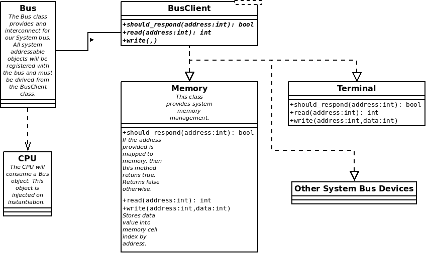
Our CPU class will be the device that controls all other devices in our system. The device in control of the bus is called the bus master. In some systems, you can have many bus masters which take turns controlling the bus. the devices on the bus that are controlled by the bus master are called bus slaves. Since the CPU controls the Bus, we will create a bus object and inject it into the CPU on instantiation.
I/O devices that wish to connect as slaves to the system bus must incorporate the BusClient interface shown above. An interface is simply a contract between two classes to use certain means of signaling and communications. Our BusClient interface says that the slave and the master agree to communicate using three methods: First, the should_respond() method takes an address and allows the slave device to determine if it should respond to the address passed to the method. Second, is the read() and write() methods. In the class diagram, you can see that the terminal and memory classes implement this contract. This all sounds rather complicated but in fact, is very simple. It’s only the jargon that makes it sound scary for new developers.
Before we can write our CPU we will need a system bus to connect the CPU too. So let’s implement the Bus class and the BusClient interface.
#!/usr/bin/env python3
# -*- coding: utf-8 -*-
# File: bus.py

""" Tiny-T CPU Simulator.
Tiny-T is a simple CPU Simulator intended as a teaching
aid for students learning about computer architecture."""

from abc import ABC


class BusClient(ABC):
    @staticmethod
    def should_respond(address, is_io_request=False):
        pass

    @staticmethod
    def read(address: int) -> int:
        pass

    @staticmethod
    def write(address: int, data: int):
        pass


class Bus:
    def __init__(self):
        self.data = 0
        self.address = 0
        self.handlers = []
        self.is_io_request = False

    def register_handler(self, handler: BusClient):
        try:
            self.handlers.append(handler)
        except:
            raise TypeError(f'Attempt to register a handler of type {type(handler)}. Handlers must be of type '
                            f'callable.')

    def set_io_request(self):
        self.is_io_request = True

    def clear_io_request(self):
        self.is_io_request = False

    def read(self, address):
        if self.is_io_request:
            address = address & 0xFF
        self.data = None
        self.address = address
        for handler in self.handlers:
            if handler.should_respond(address, self.is_io_request):
                self.data = handler.read(address)
        return self.data

    def write(self, address, data):
        if self.is_io_request:
            address = address & 0xFF
        self.data = data
        self.address = address
        for handler in self.handlers:
            if handler.should_respond(address, self.is_io_request):
                handler.write(address, data)
Our Bus class contains just five methods. First is the register_handler() method. This method receives objects that wish to connect to the bus. These objects must implement the BusClient interface contract to be able to register. This insures the devices registered can communicate with the bus and vice versa.
The registration method simply collects all the bus slave objects into a list. Later, the read() and write() methods use this list to communicate with each registered device and ask them if they wish to respond to the request being made.
The read() method loops through the list of objects and calls the should_respond() method on each object in the list. The object then checks the address and the state of the is_io_request flag passed in, to determine if it should respond to the request.
The write() method also calls the object’s should_respond() method in the same manner as the read() method did. Once a device has responded with a boolean True, the device is then written to.
The Same three methods are used for I/O devices like the Terminal class. The difference here is that the I/O port address can only be a maximum of 255. Before doing any I/O requests, the processor must signal the request is an I/O request by setting the is_io_request flag on the bus object. The read() and write() methods will then mask off the upper 4-bits of our 12-bit address to ensure the port address is never larger than 255. This isn’t needed here, since we have control of the address value. However, in a real hardware system, the CPU may “float” the unused address lines allowing random values to be placed on them.
Once an I/O request has been processed, the CPU must clear the is_io_request flag, or the next memory operation will fail.
Implementing the Tiny-T CPU
Now that we have our system bus we will need a CPU to drive it. Let’s get started:
#!/usr/bin/env python3
# -*- coding: utf-8 -*-
# file: cpu.py

""" Tiny-T CPU Simulator.
Tiny-T is a simple CPU Simulator intended as a teaching
aid for students learning about computer architecture."""


from bus import Bus

class CPU:

    def __init__(self, bus: Bus):
        self.accumulator = 0
        self.program_counter = 0
        self.instruction_register = 0
        self.address_register = 0
        self.z_flag = 0
        self.p_flag = 0
        self.bus = bus
        self.active = True
The first thing we do is to import our system bus class. We need to pass the bus into the CPU constructor. In the constructor, we initialize our accumulator, program counter, instruction register, CPU flags, system bus, and a few other items. The active flag is used to halt the CPU.
Next, we need to add a method to the CPU to set the accumulator value and condition flags P and Z as they depend only on the contents of the accumulator:
    ...

        def set_accumulator(self, value):
        # Set Zero flag
        if value == 0:
            self.z_flag = True
        else:
            self.z_flag = False

        # Set Positive flag
        if value & 0b1000_0000_0000_0000:
            self.p_flag = False
        else:
            self.p_flag = True

        # Write value into accumulator
        self.accumulator = value & 0xFFFF
With this, we now need to be able to fetch an instruction. Our fetch must request the system bus to read memory, passing the address of the memory location to read data from. The bus then will call all registered devices and inquire if any wish to respond to the request. Those wishing to respond must return a boolean True.
Be aware that bus contention is possible if more than one device responds to any specific address. In that case, the last device to respond will win, and its data will be placed on the bus for the CPU to read. When working with real hardware, this is called a bus contention and will often destroy electronic components as one device outputs a high on a specific bit while the other device outputs a low on that same bit. This causes a large current to be drawn through the circuit. This high current usually results in the magic smoke being released. And, we all know that no electronic device can function properly without its magic smoke!
To handle the bus requests we will write two small methods:
    ...

    def bus_read(self, address) -> int:
        return self.bus.read(address)

    def bus_write(self, address, value):
        self.bus.write(address, value)
Now we have our methods for making read and write requests to the bus, we can write our fetch() method:
    ...

    def fetch(self, address: int):
        address = address & 0xFFF
        result = self.bus_read(address)
        return result
As long as we’re dealing with reads and writes, let’s complete this set of methods with a CPU write() method:
    ...

    def write(self, address: int, value: int):
        self.bus_write(address, value)
Now that we have most of the support methods out of the way, we will move on to handling the fetch-decode-execute cycle. We already have our fetch() method. Now we need a decode() method. Decoding our instructions is a snap. All we have to do is strip off the most significant nibble of our 16-bit instruction. This will become the opcode. The remaining 12-bits will be our operand. I used a couple of mask values to accomplish this:
    ...

    def decode(self, instr):
        # Split opcode and operand
        return (instr & 0xF000) >> 12, instr & 0x0FFF
Pretty simple right? Now we could fetch and decode program instructions if we had some memory. We’ll get to that in a bit. Right now we need to handle the execution of the instructions. Before Python 3.10, this meant using a very long “if-elif” statement or using some form of dynamic dispatching. With Python 3.10, however, we have a new language construct for conditional matching. It is the “match-case” command. I’ve waited for decades for the Python developers to add a switch-case statement like that in C-type languages. Now that we have it, I’ll be using it! If you want this code to run with python versions below 3.10, you’ll need to convert this code to the old “if-elif” form:
    ...

    def execute(self, opcode, operand):
        match opcode:
            case 0x0:
                self.__impl_halt()
            case 0x1:
                self.__impl_load(operand)
            case 0x2:
                self.__impl_store(operand)
            case 0x3:
                self.__impl_add(operand)
            case 0x4:
                self.__impl_sub(operand)
            case 0x5:
                self.__impl_and(operand)
            case 0x6:
                self.__impl_or(operand)
            case 0x7:
                self.__impl_xor(operand)
            case 0x8:
                self.__impl_not()
            case 0x9:
                self.__impl_shift_left()
            case 0xA:
                self.__impl_shift_right()
            case 0xB:
                self.__impl_branch_always(operand)
            case 0xC:
                self.__impl_branch_positive(operand)
            case 0xD:
                self.__impl_branch_zero(operand)
            case 0xE:
                self.__impl_input(operand)
            case 0xF:
                self.__impl_output(operand)
            case _:
                raise ValueError(f"Illegal opcode: {opcode}")
One thing to note here is the use of the underscore in the last case statement. The underscore is matched when nothing else matches and should always be the last case statement.
Now we need to implement all these unimplemented methods to handle each operation of the CPU. I won’t go into detail on them as the code is pretty simple to follow:
    ...

    def __impl_halt(self):
        self.active = False

    def __impl_load(self, operand: int):
        self.set_accumulator(self.fetch(operand))

    def __impl_store(self, operand: int):
        self.write(operand, self.accumulator)

    def __impl_add(self, operand: int):
        value = self.fetch(operand)
        _sum = self.accumulator + value
        self.set_accumulator(_sum)

    def __impl_sub(self, operand: int):
        value = self.fetch(operand)
        diff = self.accumulator - value
        self.set_accumulator(diff)

    def __impl_and(self, operand: int):
        value = self.fetch(operand)
        result = self.accumulator & value
        self.set_accumulator(result)

    def __impl_or(self, operand: int):
        value = self.fetch(operand)
        result = self.accumulator | value
        self.set_accumulator(result)

    def __impl_xor(self, operand: int):
        value = self.fetch(operand)
        result = self.accumulator ^ value
        self.set_accumulator(result)

    def __impl_not(self):
        result = ~self.accumulator
        self.set_accumulator(result)

    def __impl_shift_left(self):
        result = self.accumulator >> 1
        self.set_accumulator(result)

    def __impl_shift_right(self):
        result = self.accumulator << 1
        self.set_accumulator(result)

    def __impl_branch_always(self, operand: int):
        self.program_counter = operand

    def __impl_branch_positive(self, operand: int):
        if self.p_flag:
            self.program_counter = operand

    def __impl_branch_zero(self, operand: int):
        if self.z_flag:
            self.program_counter = operand

    def __impl_input(self, operand: int):
        # IO operations must set bus io request flag
        # or the following read/write operations will
        # be interpreted as a memory address space
        # operation.
        self.bus.set_io_request()
        ch = self.bus_read(0xFE)
        self.set_accumulator(ch)
        self.bus.clear_io_request()

    def __impl_output(self, operand: int):
        # IO operations must set bus io request flag
        # or the following read/write operations will
        # be interpreted as a memory address space
        # operation.
        self.bus.set_io_request()
        ch = self.accumulator
        self.bus_write(0xFF, ch)
        self.bus.clear_io_request()
Now our CPU is almost complete. We still need a couple of methods to cycle the CPU. I’ll use a step() to handle on CPU cycle, and a run() convenience method to continue stepping through the code:
    ...

    def step(self):
        self.instruction_register = self.fetch(self.program_counter)
        self.program_counter += 1
        opcode, operand = self.decode(self.instruction_register)
        self.execute(opcode, operand)

    def run(self):
        while self.active:
            self.step()
    ...
I placed these methods right between decode() and execute(). It makes the most sense there. It allows you to read the code from top to bottom and encounter the code as it will be called.
Adding Memory
With the CPU out of the way, we need memory to store our programs and data. In TIny-P CPU, we used a simple array. However, a simple array can’t be connected to the system bus. To handle this, we will create a Memory class. This class needs to connect to the system bus and follow the interface contract given by the BusClient class, we have to write the class in such a way that our static methods can access certain class properties.
For example, our Memory class will use an array (list) internally to store our data. To make this list accessible in our static methods it must be a class property. In Python, class properties are similar to static variables in C-type languages. In Python, these properties are bound to the class and not the instance. Once we have them and can access them using the class name as in Memory.bit_mask for a property named bit_mask on the Memory class.
Our Memory also needs to know where it lives in the address space. We the start_address property and the size property to determine the address space consumed by the memory. The size and bit-width are passed into the constructor. The start_address, defaults to zero and can be set with a call to set_location().
#!/usr/bin/env python3
# -*- coding: utf-8 -*-
# File: memory.py

from random import randint
from bus import BusClient


class Memory(BusClient):
    mem = []
    start_address = 0
    end_address = 4096
    bit_mask = 0

    def __init__(self, size: int, bit_width: int, read_only=False):
        self.bit_width = bit_width
        self.size = size
        self.read_only = read_only
        Memory.bit_mask = (1 << bit_width) - 1
        Memory.start_address = 0
        Memory.end_address = Memory.start_address + size
        self.clear()

    def clear(self):
        Memory.mem = [0 for _ in range(self.size)]

    def fill(self, value: int):
        Memory.mem = [value for _ in range(self.size)]

    def random_fill(self):
        Memory.mem = [(randint(0, Memory.bit_mask)) for _ in range(self.size)]

    def set_location(self, start_address: int):
        Memory.start_address = start_address
        Memory.end_address = Memory.start_address + self.size

    @staticmethod
    def should_respond(address, is_io_request=False) -> bool:
        # TODO : test for off by one error
        if Memory.start_address <= address <= Memory.end_address and not is_io_request:
            return True
        return False

    @staticmethod
    def read(address: int):
        # Note during a cpu read cycle the ram puts data on the data bus
        try:
            return Memory.mem[address]
        except IndexError:
            ValueError('Address out of range or Memory not initialized')

    @staticmethod
    def write(address: int, data: int):
        # during a cpu write cycle the ram accepts data from the data bus
        Memory.mem[address] = (data & Memory.bit_mask)

    def dump(self, start_addr: int, end_addr: int) -> str:
        rep = 'Memory Dump:\n'
        for addr in range(start_addr, end_addr + 1):
            if addr % 16 == 0:
                if addr != 0:
                    rep += '\n'
                rep += ''.join(f'0x{addr:04x} : ')
            rep += ''.join(f'0x{Memory.mem[addr]:04x} ')
        return rep + '\n'

    def __str__(self) -> str:
        rep = 'Memory Dump:\n'
        for addr in range(self.size):
            if addr % 16 == 0:
                if addr != 0:
                    rep += '\n'
                rep += ''.join(f'0x{addr:04x} : ')
            rep += ''.join(f'0x{Memory.mem[addr]:04x} ')
        return rep + '\n'

    def __repr__(self) -> str:
        return self.__str__()
In addition to the read(), write(), and should_respond() methods required by the interface, I’ve added a few convenience methods; clear() sets every cell in the memory to zero. fill() allows the user to pass a value to fill the memory cells with, and random_fill() fills the memory with random values just as a real ram would be on power-up.
I also added a dump() method to display a range of memory cells and the Python __str__() and __repr__() methods to aid in printing out the memory contents as an object representation.
Cold Boot!
At this point, we have just enough code to try out our new CPU. Create a new file named main.py. Add the following code:
#!/usr/bin/env python3
# -*- coding: utf-8 -*-
# File: main.py

from cpu import CPU
from memory import Memory
from bus import Bus

if __name__ == '__main__':
    # Instantiate System Bus Object
    bus = Bus()

    # Create System Memory
    ram = Memory(32, 16)
    ram.clear()
    ram.set_location(0x000)
    # Register Memory on bus
    bus.register_handler(ram)

    # Instantiate CPU and attach to bus
    cpu = CPU(bus)

    # Program
    cpu.write(0x0000, 0x1001)  # LDA (0x001)
    cpu.write(0x0001, 0x00FF)  # Data Value 0x00FF
    cpu.write(0x0002, 0x0000)  # HLT - Halt CPU

    # Execute
    cpu.step()
    cpu.step()
    cpu.step()
    cpu.step()
As an exercise, add a function to main.py to print out the CPU’s status including the accumulator contents, program counter value, P and Z flags, and the memory contents from 0x000 to 0x020. Call the function before the first call to cpu.step() and after each additional call to cpu.step(). Follow the program and make sure it works as expected. Then write tests for all but the INP and OUT instructions as these will fail until we add some I/O to the system.
Conclusion
We covered a lot of ground today! However, if you’ve been following this series of posts, you should be able to follow this post as it builds upon previous articles. While I find this a good place to stop for today, the project is by no means complete. We will continue next time with the addition of a terminal.
Resources
The code for this article series can be found at: https://github.com/Monotoba/Building-Machines-In-Code.git